





1. The Actual Meaning of Resolution
Resolution refers to the minimum reading unit that the instrument's optical scale (or encoder) can display. In the VMM industry, a commonly seen resolution specification is 0.001 mm (i.e., 1 μm), though this value serves only as a general industry reference, and actual configurations may vary across manufacturers and models. Resolution reflects the subdivision capability of the display system — how small an increment the instrument can "read" — but it does not represent how accurately the instrument can "measure." Consider a steel ruler with 1 mm graduation spacing: if the graduation lines themselves carry a width error of 0.5 mm, then even if the reading reaches the 1 mm mark, the actual measurement result may still deviate by 0.5 mm. Resolution addresses the question of "how fine the reading is"; accuracy addresses "how correct the reading is."
2. The Correct Criterion for Accuracy: MPE_E
The actual measurement accuracy of an instrument should be determined based on the Maximum Permissible Error of Indication (MPE_E) stated in its inspection report. MPE_E is typically expressed as a formula related to the measured length (L, in mm), meaning that the permissible deviation between the instrument's indication and the true value differs across different measured lengths. The general rule is: the larger the measured length, the wider the permissible error range.
This means that the same instrument will have different permissible errors when measuring a 10 mm feature versus a 200 mm feature. Therefore, a single resolution figure cannot determine whether an instrument meets the tolerance requirements of a specific workpiece. The actual length of the measured dimension and the corresponding MPE_E value must be considered together.
It is worth noting that some instrument manufacturers label their products with qualitative descriptions such as "micron-level precision" in product literature without publishing specific MPE_E values. Such descriptions only indicate the order of magnitude of accuracy and cannot replace an inspection report for tolerance determination. During the selection phase, a complete factory inspection report should be requested directly from the supplier.
3. Typical Manifestations in Production
This conceptual confusion typically manifests in practice as follows: a workpiece has a drawing tolerance of ±0.01 mm, and the user employs a VMM with a stated resolution of 0.001 mm for inspection, reasoning that the resolution is far smaller than the tolerance and should therefore be sufficient. However, in actual measurement, repeated measurements of the same feature show noticeable variation, and repeatability falls short of expectations.
This situation is usually not caused by insufficient resolution. A resolution of 0.001 mm merely means that the display reads to three decimal places. The factors affecting measurement result stability — including thermal drift of the Z-axis column, straightness errors and stick-slip in the guide rails, and installation errors of the optical scale — can introduce deviations at the micron level, far exceeding the accuracy level implied by the resolution. To address such issues, the mechanical system must be inspected and, if necessary, re-compensated for errors, rather than relying on a higher resolution specification.
4. Selection and Usage Recommendations
During instrument selection, a complete inspection report should be requested from the supplier, with particular attention to the specific MPE_E values at different length ranges. These values should be compared against the tolerance requirements of the intended products. As a general guideline, the instrument's MPE_E should fall within 1/3 to 1/5 of the workpiece tolerance to ensure sufficient decision margin in the measurement results.
During use, resolution should not serve as the direct basis for tolerance determination. For critical dimensions, it is recommended to assess actual measurement capability through repeated measurements and verification with reference standards, rather than relying solely on the number of displayed digits.
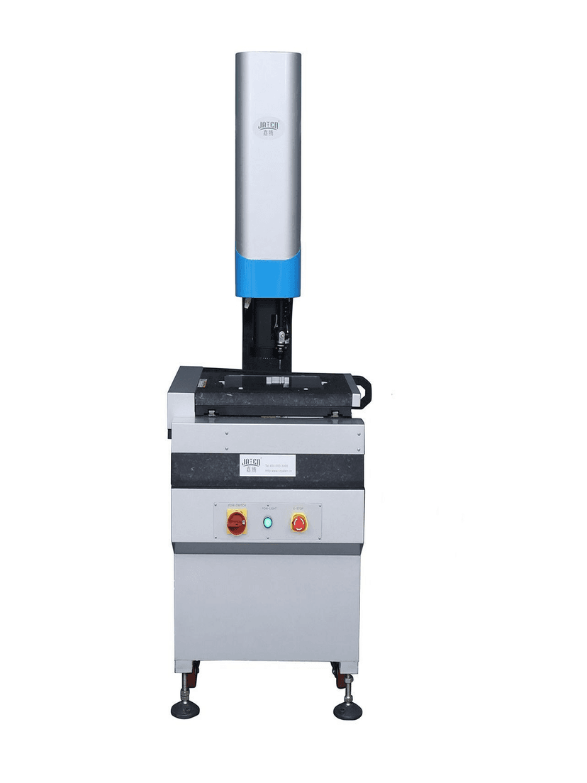
Taking JATEN video measuring systems as an example, the JTDIM-200 is described in product literature as offering "micron-level precision," equipped with precision linear scales, a telecentric optical system, and a granite base. The JTDIM3020 features dual 20-megapixel CCDs paired with bilateral telecentric lenses (ultra-low distortion), a Mitsubishi three-axis servo drive system, and a self-developed programmable light source control system with a built-in brightness sensor. The two models differ in their hardware configurations, but for both, actual measurement accuracy must be verified against the MPE_E data in the factory inspection report and evaluated in the context of the specific application scenario to ensure reliable measurement results.
For more details, please visit: https://www.jatentech.com/products/video-measuring-machine