





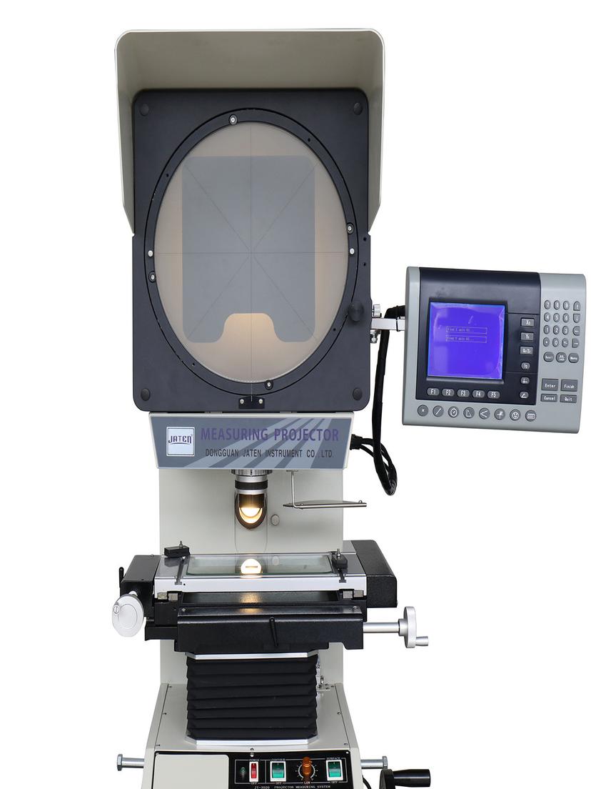
The JTDHB12 is a horizontal profile projector: optical axis horizontal, screen vertical. A part sits on the stage, light comes from behind, the objective magnifies the contour, and the screen receives it. Five components carry that chain — stage, illumination, objective, screen, and readout — in the order a part travels through them.
1. The Work Stage: Where the Part Sits
The stage is a metal table, 408 x 126 mm, with 200 mm X travel, 100 mm Z travel, and 0.0005 mm linear resolution on both. The third axis, Y, focuses over 75 mm.
Each axis has a job: X moves sideways, Z advances, Y raises for focus. The part moves with the table, the readout records the distance, and that is where a dimension comes from.
The table also swivels through ±15°. On cones, tapers, and tapered threads the flank is not square to the optical axis, so the contour projects out of shape; tilt until flank and axis align.
The stage is the mechanical reference of the whole chain: however sharp the image, an unverified travel leaves no valid measurement.
2. Illumination: Two Systems, Two Jobs
Contour illumination is 24v/150w halogen shining through the part from behind; surface illumination is 21v/150w optical fibre aimed at the front.
The division is optical, not optional. Transmitted light stops at the part and leaves a clean dark silhouette for external dimensions, hole positions, and spacing. Reflected light brightens the face for what transmitted light never reaches — scribed lines, blind holes, recesses, steps.
Threads add one adjustment. The source helix sets ±7° for accurate thread form projection: a thread is helical, its flank is not square to the axis, and without tilting the beam the projected flank carries a systematic error that corrupts pitch diameter and flank angle.
3. The Objective: Where the Contour Is Magnified
The objective magnifies the contour; its power sets the ratio between screen image and part. The JTDHB12 ships with 10X standard, with 20X, 50X, and 100X available.
Magnification changes two things: the same screen distance covers a smaller feature, so detail resolves better, but the field shrinks. Low power for the whole contour, high power for a narrow edge. It is not a race to the highest number, but matching feature size to inspection cycle.
Magnification accuracy is easier to miss. Contour 0.08%, surface 0.12% — the gap between the magnified image and the theoretical magnification. At 20X a 10 mm contour should appear as 200 mm; 0.08% puts it 0.16 mm off on screen, 8 µm back on the part. That error lands in the reading, nowhere else.
4. The Projection Screen: Where Judging Happens
The contour is on the screen, the travel is on the readout, and the dimension comes from the two together.
At 300 mm diameter the screen is fully usable, carrying precision cross lines and a 90° reticle. The cross lines set the reference: aligning the contour fixes position, which the stage readout supplies, while angle comes from the screen graduation. Chart clips mount a drawing on the screen to compare against the projected contour in place, the usual origin of the name optical comparator. Overlay clips and an integral hood cut ambient light, which makes an edge easier to judge through an overlay.
The screen rotates 0-360°, its indicator resolving 1' or 0.01°. You turn the screen, not the part.
5. The DP300 Readout: Turning Travel into Data
The DP300 (561-301) is JATEN's self-developed system: multi-point sampling, coordinate rotation, point, line, distance, angle, and RS-232 export.
Multi-point sampling fits circles, arcs, and hole positions from several touches. Coordinate rotation squares a tilted setup, so a crookedly clamped part need not come off. RS-232 removes transcription and its mistakes.
6. One Measurement, Start to Finish
Clamp the part. Decide whether the shape needs the table tilted. Match the magnification to the feature. Choose the light: transmitted for external form, reflected for surface features, helix for threads. Move X and Z to put the contour on the cross lines, or overlay a drawing. Record and export.
Every step lands on a component: the wrong light leaves no edge to judge, the wrong power will not fit the part on screen, and a taper read at zero sway is not its true shape.
Accuracy is quoted as ≤3+L/200 µm, L being the measured length in millimetres. Power is AC110V/60Hz or 220V/50Hz, 650W.
7. What This Machine Measures
Parts whose contour is the acceptance criterion are the typical object. The page lists templates, stampings, cams, threads, gears, forming milling cutters, tools, terminals, watch parts, diamonds, across machinery, mould making, instrumentation, electronics, and light industry.
The horizontal layout adds a second role: it supplements a vertical projector where dimensions are hard to detect or areas hard to observe. Different clamping exposes different faces, so the two lines coexist rather than repeat.
See the [JATEN profile projector page](https://www.jatentech.com/products/profile-projector) for models and configurations.